| |
Introduction to Protection Transformers
Protective Current Transformers are designed to measure the actual
currents in power systems and to produce proportional currents in
their secondary windings which are isolated from the main power
circuit. These replica currents are used as inputs to protective
relays which will automatically isolate part of a power circuit
In the event of an abnormal or fault condition therein, yet permit
other parts of the plant to continue in operation.
Satisfactory operation of protective relays can depend on accurate
representation of currents ranging from small leakage currents to
very high overcurrents, requiring the protective current transformer
to be linear, and therefore below magnetic saturation. at values
up to perhaps 30 times full load current .This wide operating range
means that protective current transformers require to be constructed
with larger cross-sections resulting in heavier cores than equivalent
current transformers used for measuring duties only. For space and
economy reasons, equipment designers should however avoid over specifying
protective current transformers ITL technical staff are always prepared
to assist in specifying protective CT's but require some or all
of the following information
|
| |
| |
(a) Protected equipment and type of protection.
(b) Maximum fault level for stability.
(c) Sensitivity required.
(d) Type of relay and likely setting.
(e) Pilot wire resistance, or length of run and pilot wire
used.
(f) Primary conductor diameter or busbar dimensions.
(g) System voltage level.
|
|
|
| |
CAUTION : RELAY MANUFACTURER'S
RECOMMENDATIONS SHOULD
ALWAYS BE FOLLOWED
|
| |
 |
| |
IEC Specification
According to 60044-1 protective current transformers are
specified as follows:
Rated Output:
The burden including relay and pilot wires
Standard burdens are 2.5,5,75,10, 15 and 30VA
Accuracy Class:
Accuracy classes are defined as 5P or 10P with limits according
to the following table extracted from I EC 60044-1
|
|
 |
|
| |
| Accuracy Class |
Current error at rated primary
current |
Phase displacement at rated primary
current |
Composite error at rated accuracy
limit primary current |
| % |
min |
centiradians |
% |
| 5P |
"1 |
"60 |
"1.8 |
5 |
| 10P |
"3 |
|
|
10 |
|
|
|
Accuracy Limit Factor
Accuracy limit Factor is defined as the multiple of
rated primary current up to which the transformer will
comply with the requirements of 'Composite
Error' . Composite Error is the deviation from an ideal
CT (as in Current Error), but takes account of harmonics
in the secondary current caused by
non-linear magnetic conditions through the cycle at
higher flux densities.
Standard Accuracy Limit Factors are 5, 10, 15, 20 and
30. The electrical requirements of a protection current
transformer can therefore be defined as :
RATIO/VA BURDEN/ACCURACY CLASS /
ACCURACY LIMIT FACTOR.
For example: 1600/5, 15VA 5P10
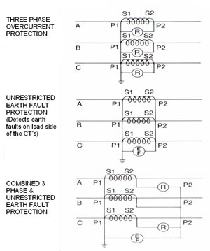
Selection of Accuracy Class & Limit Factor.
General:
Class 5P and 10P protective current transformers are
generally used in overcurrent and unrestricted earth
leakage protection. With the exception of simple trip
relays, the protective device usually has an intentional
time delay, thereby ensuring that the severe effect
of transients has passed before the relay is called
to operate. Protection Current Transformers used for
such applications are normally working under steady
state conditions Three examples of such protection is
shown. In some systems, it may be sufficient to simply
detect a fault and isolate that circuit. However, in
more discriminating schemes, it is necessary to ensure
that a phase to phase fault does not operate the earth
fault relay.
|
|
 |
|
Phase Fault Stability
Current transformers which are well matched and operating
below saturation, will deliver no current to the earth fault
relay, since 3-phase currents sum to zero. If however, the
transformers are badly matched, a spill current will arise
which will trip the relay. Similarly, current transformers
must operate below the saturation region, since, in a 3 phase
system, third harmonics in the secondary are additive through
the relay thereby creating instability and erroneously tripping
the earth fault relay.
|
|
Time Grading
Time lags on relays are set in such a way that a fault in
a sub�section will isolate that section of the distribution
only. Accurate time grading can be adversely affected by inaccuracy
or saturation in the associated current transformer. The following
table is intended to show typical examples of CT applications
However, in all cases manufacturers recommendations must be
followed.
|
| Protective System |
CT Secondary |
VA |
Class |
| Pecurrent for phase &
earth fault |
1A
5A
|
2.5
7.5
|
10P20 or 5P20
10P20 or 5P20
|
| Unrestricted earth fault |
1A
5A
|
2.5
7.5
|
10P20 or 5P20 |
| Sensitive earth fault |
1A or 5A |
|
Class PX use relay manufacturers
formulae |
| Distance protection |
1A or 5A |
|
Class PX use relay manufacturers
formulae |
| Differential protection |
1A or 5A |
|
Class PX use relay manufacturers
formulae |
| High impedance differential
impedance |
1A or 5A |
|
Class PX use relay manufacturers
formulae |
| High speed feeder protection |
1A or 5A |
|
Class PX use relay manufacturers
formulae |
| Motor protection |
1A or 5A |
5 |
5P10 |
|
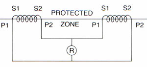
Balanced Forms of Protection
In balanced systems of protection, electrical power
is monitored by the protective CTs at two points in
the system as shown. The protected zone is between the
two CTs If the power out differs from the power in,
then a fault has developed within the protected zone
and the protection relay will operate. A 'Through Fault'
is one outside the protected zone Should such a fault
occur, the relay protecting the protected zone will
not trip, since the power out will still equal the power
in. Numerous different types of balanced systems exist
and advice may often have to be obtained from the relay
manufacturer. However, in all cases Sensitivity and
Stability must be considered.
|
|
 |
| |
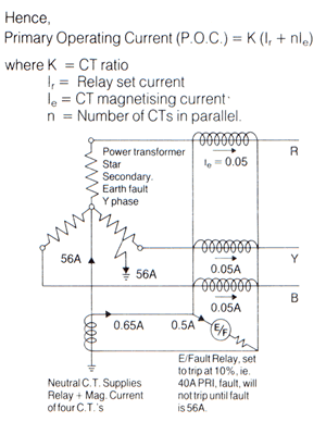
Sensitivity
Sensitivity is defined as the lowest value of
primary fault current, within the protected zone,
which will cause the relay to operate. To provide
fast operation on an in zone fault, the current
transformer should have a 'Knee Point Voltage'
at least twice the setting voltage of the relay.
The 'Knee Point Voltage' (Vkp) is defined as the
secondary voltage at which an increase of 10%
produces an increase in magnetising current of
50%. It is the secondary voltage above which the
CT is near magnetic saturation.
Differential relays may be set to a required
sensitivity but will operate at some higher value
depending on the magnetising currents of the CTs,
for example:
The diagram shows a restricted earth fault system
with the relay fed from 400/5 CTs. The relay may
be set at 10%, but it requires more than 40A to
operate the relay since the CT in the faulty phase
has to deliver its own magnetising current and
that of the other CTs in addition to the relay
operating current.
|
|
 |
Stability
That quality whereby a protective system remains
inoperative under all conditions other than those
for which it is designed to operate, i.e. an in-zone
fault Stability is defined as the ratio of the
maximum through fault current at which the system
is stable to nominal full load current. Good quality
current transformers will produce linear output
to the defined knee point voltage (Vkp).
Typically,
Vkp = 2If(Rs+Rp) for stability, where
If = max through fault secondary current at
stability limit
Rs = CT secondary winding resistance
Rp = loop lead resisitance from CT to relay
|
Transient Effects
Balanced protective systems may use time lag
or high speed armature relays. Where high speed
relays are used, operation of the relay
occurs in the transient region of fault current,
which includes the d c asymmetrical component.
The build up of magnetic flux may therefore be
high enough to preclude the possibility of
avoiding the saturation region.
The resulting transient instability can fortunately
be overcome using some of the following
techniques.
a) Relays incorporating capacitors to block the
dc asymmetrical component.
b) Biased relays, where dc asymmetrical currents
are compensated by anti phase coils.
|
|
(c) Stabilising resistors in series with current
operated relays, or in parallel with voltage operated
relays. These limit the spill current
(or voltage) to a maximum value below the
setting value. For series resistors in current
operated armature relays.
Rs = (Vkp/2) - (VA/Ir)
where:
Rs = value of stabilising resistor in ohms
Vkp = CT knee point voltage
VA = relay burden (typically 3VA)
Ir = relay setting current
Note:
The value of Rs varies with each fault setting.
An adjustable resistor is therefore required for
optimum results. Often a fixed resistor suitable
for mid-setting will suffice.
|
Class PX Protection CT's
Class 5P protection current transformers may
be adequate for some balanced systems, however
more commonly, the designer will specify a special
'Class PX' CT giving the following information.
|
|
(a) Turns ratio.
(b) Knee point voltage Vkp.
(c) Maximum exciting current al Vkp.
(d) CT secondary resistance.
|
| Apparatus |
Protective System |
Min. Stability
Limit x Rated Current |
| Generator &
Synchronous Motors |
Differential Earth Fault
Longitudinal Differential
|
12.5
12.5
|
| Transformers |
Differential Earth Fault
Longitudinal Differential
|
16
16
|
| Induction Motors
/ Busbars Feeders |
Differential Earth Fault
Longitudinal Differential
|
1.25x Starting
Current, 1x Switchgear short-circuit rating,
short circuit rating, 30 |
|
|
|
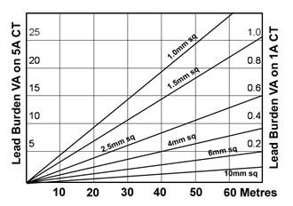
Pilot Wire Burden for Class PX CTs
For 'Class X' current transformers, the cross section
and length of pilot wires can have a significant effect
on the required Vkp and
therefore the size and cost of the CT. When the relay
is located some distance from the CT, the burden is
increased by the resistance of the pilot wires.
The graph shows the additional burden of pilot leads
of various diameters. It should be noted that, by using
a 1 amp instrument and CT, the VA burden imposed by
the pilot wires is reduced by a factor of 25.
|
|
 |
|
|
| |
|
|