|
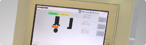
Based on an embeded Windows XP System, the BGD5 offers simple
WYSIWYG programming, with full graphical interface. No CNC
programming skills are required with even the most complicated
busbar configurations easily created / edited.
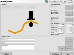
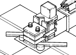
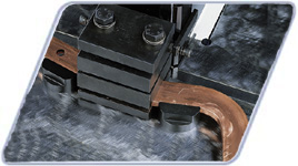
During bending operation the digital angle measurement with
full automatic spring back compensation will ensure an accuracy
of +/- 0.2 degrees from requested value. The automatic length
stop will travel up to 800mm positioning your busbar within
seconds. With an intigrated 3Ph/400V power pack minimising
cycle times to around 11 seconds for a 90 degree bend including
the spring back competnsation
Advantages at a Glance:
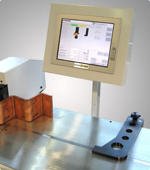
- Latest Windows XP technology with 12" LCD monitor
- Unmatched, full graphical WYSIWYG programming
- USB and LAN for backups and remote editing
- Digital encoder with an accuracy to 0.2 degrees
- Full automatic spring back compensation
- No trial bends, No setup time
- Digital stroke encoder for minimum cycle time
- Intigrated high performance 3Phase power pack
- Optional step and edgebending tools
- Tight U and Z bends possible
- Mobile for ease of movement within workshop
| Technical Specifications
- Incl Automatic Lentgh Stop Part 41800 |
| Depth |
900mm |
| Width |
1630mm |
| Height |
1530mm |
| Weight |
370Kg |
| Hydraulic Pressure |
200 bar max. (3000psi) |
| Max. Busbar Size |
160x13mm (6"x1/2") |
| Length Stop Travel |
800mm |
| Bending Radius Adapters |
7.5, 10.0 and 15.0mm |
| Power Rating |
1.2kW |
| Voltage |
3~400V/50Hz |
| Oil Flow |
3.6 l/min |
| Cycle time* |
11.5 sec. |
| Cycle time** (repeat operation) |
9.4 sec, |
| Minimum L-Bend |
25mm |
| Minimum U-Bend |
60mm |
| Minimum Z-Bend |
70mm |
* 90 Degree bend 120x10mm busbar size return stroke including
full automatic spring back compensation
** 90 Dgree bend 120 x 10mm busbar size repeat operation
|