| |
Introduction to Measurement Transformers
Measuring instruments, such as ammeters, voltmeters, kilowatt-hour
meters, etc , whether electromechanical or electronic, meet insuperable
design problems if faced with the high voltages or high currents
commonly used in power systems. Furthermore, the range of currents
employed throughout is such that it would not be practical to manufacture
instruments on a mass production scale to meet the wide variety
of current ranges required.
Current transformers are therefore used with the measuring instruments
to: (a) Isolate the instruments from the power circuits. (b) Standardise
the instruments, usually at 5 amps or 1 amp. The scale of the instrument
(according to the C T ratio), then becomes the only non-standard
feature of the instrument.
|
| |
Accuracy Class
Accuracy classes for various types of measurement are set out in
BSEN /IEC 60044-1. It will be seen that the class designation is
an approximate measure of the accuracy, e g , Class 1 current transformers
have ratio error within 1% of rated current. Phase difference is
important when power measurements are involved, i.e. when using
wattmeter's, kilowatt-hour meters, VAr meters and Power Factor meters.
|
|
| Class |
% current ratio at % of ratio current
shown below. |
Applications |
| 50 |
120 |
| 3 |
3 |
3 |
Ammeters |
| 5 |
5 |
5 |
Approximate Measurements |
|
| |
| Accuracy |
% current ratio error at % of rated
current shown below |
Phase displacement (minutes) at
% of rated current shown below |
Applications |
| Class |
5 |
20 |
100 |
120 |
5 |
20 |
100 |
120 |
| 0.1 |
0.4 |
0.2 |
0.1 |
0.1 |
15 |
8 |
5 |
5 |
Precision Testing & Measurement |
| 0.2 |
0.75 |
0.35 |
0.2 |
0.2 |
30 |
15 |
10 |
10 |
Precision Grade Meters |
| 0.5 |
1.5 |
0.75 |
0.5 |
0.5 |
90 |
45 |
30 |
30 |
Tarriff kWh Metering |
| 1.0 |
3.0 |
1.5 |
1.0 |
1.0 |
180 |
90 |
60 |
60 |
Commercial kWh Metering |
|
| |
The table below details limits of error for current transformers
for special applications and having a secondary current of 5A
|
| |
| Accuracy |
% current ratio error at % of rated
current shown below |
Phase displacement (minutes) at
% of rated current shown below |
| Class |
5 |
20 |
100 |
120 |
120 |
5 |
20 |
100 |
120 |
120 |
| 0.2s |
0.75 |
0.35 |
0.2 |
0.2 |
0.2 |
30 |
15 |
10 |
10 |
10 |
| 0.5s |
1.5 |
0.75 |
0.5 |
0.5 |
0.5 |
90 |
45 |
30 |
30 |
30 |
|
| |
|
|
|
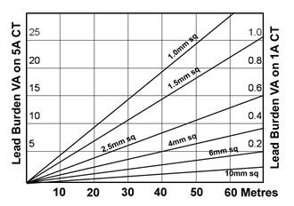
Meter & Pilot Lead Burden
Burden is the load imposed on the secondary of the CT at
rated current and is measured in VA (product of volts and
amps). The accuracy class applies only to loads at rated VA
and below, down to one quarter VA .The burden on the secondary
of a CT includes the effect of pilot leads, connections etc
, as well as the instrument burden itself.
In situations where the meter is remote from the current
transformer, the resistance of the pilot wires may exceed
the meter impedance many times in these cases it is often
economical to use 1 amp meters and CTs.
The diagram shows the burden imposed on the CT due to a run
of pilot wire. It will be seen that a pilot loop of 2.5mm2
wire, 60 metres long (30 metres distance) has a load of 12.5
VA on a 5 amp CT but only 0.5VA on a 1 amp CT.
|
|
 |
| |
|
|
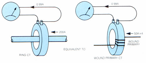
Wound Primary CTs
Thus, current transformers for 80 amps and
below frequently require more than 1 turn to achieve the desired
accuracy class. Considering again the previous example.
Using the same core and by winding 200 secondary turns and
4 primary turns a 50/1 ratio is achieved. The magnetising
ampere turns
remains at 2 as before, however the magnetising current becomes
2 divided by 4 turns or 0.5A and the percentage error is reduced
to 1% (approx.).
It is therefore possible to achieve accuracy requirements,
without using expensive core materials, by constructing a
wound primary transformer. Of course, the cost of the primary
winding with its insulation and terminations must be weighed
against the cost of the more expensive core which would be
required to achieve a 1% accuracy for a ring CT at a 50/1
ratio.
|
Ampere Turns Rule
An ideal transformer is based on the Amperre Turns Rule,
i.e. Primary Ampere Turns = Secondary Ampere Turns or: IpTp
= IsTs (Ts/Tp=Ip/Is)
Thus the current transformation ins in INVERSE proportion
to turns whereas voltage transformersion is in DIRECT proportion
to turns ie Ts/Tp=Vs/Vp
|
Design Considerations
As in all transformers, errors arise due to a proportion
of the primary input current being used to magnetise the core
and not transferred to the secondary winding. The proportion
of the primary current used for this purpose determines the
amount of error.
The essence of good design of measuring current transformers
is to ensure that the magnetising current is low enough to
ensure that the error specified for the accuracy class is
not exceeded.
This is achieved by selecting suitable core materials and
the appropriate cross-sectional area of core. Frequently in
measuring currents of 50A and upwards, it is convenient and
technically sound for the primary winding of a CT to have
one turn only.
In these most common cases the CT is supplied with a secondary
winding only, the primary being the cable or busbar of the
main conductor which is passed through the CT aperture in
the case of ring CTs (i .e. single primary turn) it should
be noted that the lower the rated primary current the more
difficult it is (and the more
expensive it is) to achieve a given accuracy.
Considering a core of certain fixed dimensions and magnetic
materials with a secondary
winding of say 200 turns (current ratio 200/1 turns ratio
1/200) and say it takes 2 amperes of the 200A primary current
to magnetise the core, the error is therefore only 1% approximately.
However considering a 50/1 CT with 50
secondary turns on the same core it still takes
2 amperes to magnetise to core. The error is then 4% approximately.
To obtain a 1%
accuracy on the 50/1 ring CT a much larger core and/or expensive
core material is required.
|
Saturation
Magnetic materials are such that when the magnetic flux reaches
a certain value the core will saturate. At this point a large
proportion of the primary current is required to magnetise
the core Increasing the primary current in the saturation
region will therefore cause only a marginal increase in secondary
current. It is obvious that the CT is completely inaccurate
when saturated Saturation can occur if the actual burden exceeds
the rated burden, or if heavy overcurrents occur.
This phenomenon can be used to protect an instrument against
damage due to heavy overcurrent and a Saturation Factor is
sometimes specified. For example, if a Instrument Sensitivity
Factor (Fs) of less than 5 is specified, the CT must be designed
to ensure that, at the rated burden, the core is well into
the saturation region (defined point) at 51 times the rated
primary
current.
It is critical that the actual burden is established to ensure
the saturation factor is complied with. Fs is the ration of
instrument limit primary current to the rated primary current.
The lower the factor the higher the degree of safety. However
it is not always practical to achieve a high accuracy class
with an extremely low instrument security factor.
|
Open Circuit Current Transformers
It is important to ensure that the secondary of any CT is
not left disconnected while the primary supply is on. In this
condition, high voltage spikes are produced in the transformer
secondary, often thousands of volts, sufficient to break down
the transformer insulation.
|
| |
Dual or Multi-Ratio Transformers
Frequently when a new plant is commissioned, it is planned
for further extension and consequent increase in power consumption.
In this event, it may be advisable to install dual ratio CTs
with a tapped secondary to allow alterations to the metering
without the expense and disruption of replacing the CTs. In
this case, the unused terminal should be left open-circuit.
|
Construction of Measuring Current Transformers
Measuring current transformers are available in a variety
of different forms and terminations to meet the requirements
of the particular installation.
Taped Ring CTs
(R Range)
Suitable for Indoor use, are probably the most common type
of CT Installed in LV switchgear and control gear Circular
cores wound in clock spring fashion provide a near ideal magnetic
circuit, free of air gaps and having very low leakage or stray
fields. After applying suitable robust insulation to these
cores, the windings are applied evenly around the cores by
toroidal winding
machines. Taped ring CTs are a so used extensively in HV switchgear
and power transformers where the insulation is provided by
the HV bushings. Where CTs are to be installed under hot oil,
insulation materials have to be selected to avoid pollution
of the oil. Rectangular core CTs are also available to suit
applications where space is very restricted.
Enclosed Plastic Moulded Case
Current Transformers (M Range)
Similar to the ring CTs but enclosed in tough injection moulded
shells to provide a clean and uniform appearance. Mounting
brackets and facilities for busbar clamps and other accessories
can be incorporated in the mould design thereby resulting
in a lower cost unit. The speed and simplicity with which
moulded case CTs can be clamped to busbars is an important
feature of the unit.
|
Legacy
Model MT0 - Discontinued
|
Legacy Model MWBD -
Contact us for
more information |
|
|
Legacy
Model MT21 - Discontinued
|
|
|
|
Legacy Model MT33 - Discontinued
|
|
|
|
Legacy
Model M4085 - Discontinued
|
Legacy
Model MT53 - Discontinued
|
Legacy
Model MT61 - Discontinued
|
|
|
|
|
|
|
|
|
| |
|
|
|
|
|
|
|
|
|
|
|
|
|
|
|
|
|
|
|
|
|
|
|
|
|
|
|
|
| |
|
|
|
|
|
|
|
|
|
|
|
|
|
|
|
|
Resin Cast Current Transformer
Produced by casting the transformer in liquid resin which
is then cured to the solid state. These transformers are expensive,
but they are robust and immune to difficult climatic conditions.
Special resins are now available to make the transformers
suitable for outdoor use. Resin Cast CTs are commonly used
at high voltages, up to 33kV. In these applications, highly
controlled casting techniques are required to avoid air voids
where corona discharge could effect the quality of insulation.
|
| |
|
|
|
| |
|
| |
|
| |
|
|